An ignition switch wiring diagram is a visual guide illustrating the electrical connections within an ignition system. It helps technicians and DIYers understand how components interact, ensuring proper installation and troubleshooting. These diagrams are essential for diagnosing issues like no power or intermittent faults, providing a clear map of the circuitry. Always refer to vehicle-specific diagrams for accuracy and safety.
What is an Ignition Switch Wiring Diagram?
An ignition switch wiring diagram is a detailed visual representation of the electrical connections within an ignition system. It illustrates how components like the ignition switch, battery, starter motor, and ignition coil are interconnected. The diagram uses symbols and color-coded wires to simplify troubleshooting and installation. Available as PDF guides, these diagrams provide a clear map of the circuitry, ensuring proper functionality and safety; They are essential for understanding power distribution and diagnosing issues like no-start conditions or intermittent electrical faults in vehicles.
Importance of Understanding the Diagram
Understanding an ignition switch wiring diagram is crucial for diagnosing and repairing electrical issues in a vehicle’s ignition system. It helps identify faulty components, such as a malfunctioning ignition coil or damaged wires, ensuring proper power distribution. By recognizing circuit connections, technicians can prevent short circuits and ensure safety during repairs. The diagram also guides the installation or replacement of ignition switches, helping maintain system reliability. Referencing a PDF guide specific to your vehicle ensures accuracy and adherence to manufacturer recommendations for optimal performance and safety.

Components of the Ignition System
The ignition system consists of the ignition switch, battery, starter motor, ignition coil, and fuses/circuit breakers. These components work together to supply power, start the engine, and regulate electrical flow safely.
The Ignition Switch
The ignition switch is a critical component that controls the flow of electrical power to the engine and accessories. It operates in multiple positions (OFF, RUN, START) to activate the starter motor and ignition system. The switch connects to the battery, ignition coil, and starter, ensuring proper power distribution. Its terminals are color-coded for easy identification. A faulty ignition switch can cause starting issues or electrical malfunctions. Always refer to a vehicle-specific wiring diagram for accurate connections and safe repairs.
The Battery
The battery is the primary power source for the ignition system, providing the necessary voltage to activate the starter motor and ignition coil. It is connected directly to the ignition switch and starter motor, ensuring power is distributed correctly when the ignition is turned on. The battery’s positive terminal is linked to the ignition switch, while the negative terminal is grounded to complete the circuit. Proper battery connections are essential for reliable engine starting and overall electrical system functionality. Always verify battery health and connections before diagnosing ignition issues.
The Starter Motor
The starter motor is a critical component in the ignition system, responsible for turning the engine over during startup. It is connected to the ignition switch via a circuit that includes a relay or solenoid. When the ignition switch is in the “start” position, it sends an electrical signal to the starter motor, engaging it to crank the engine. The wiring diagram shows the connections between the ignition switch, battery, and starter motor, ensuring proper power flow. Regular inspection of these connections is essential for reliable engine starting and preventing potential issues.
The Ignition Coil
The ignition coil is a vital component in the ignition system, responsible for generating the high voltage needed to create sparks in the engine’s cylinders. It is connected to the ignition switch and spark plugs through a wiring circuit. The ignition switch controls the power supply to the coil, ensuring voltage is delivered only when the engine is in the “run” or “start” position. A wiring diagram helps trace these connections, showing how the coil interacts with other components like the battery and spark plugs. Proper wiring ensures efficient combustion and reliable engine operation.
Fuses and Circuit Breakers
Fuses and circuit breakers are essential for protecting the ignition system from electrical overloads. They act as safety devices, interrupting the circuit to prevent damage. Typically located in the fuse box, they are connected in series with critical components like the ignition switch and coil. A wiring diagram helps identify which fuses control specific circuits, ensuring quick troubleshooting. Replacing a blown fuse or resetting a breaker restores power to the ignition system. Always consult the vehicle-specific diagram to locate and verify fuse types and ratings for safe repairs.

How to Read an Ignition Switch Wiring Diagram
Understanding symbols, color codes, and connections is key to interpreting wiring diagrams. Trace circuits carefully, ensuring each wire’s purpose aligns with the ignition system’s functionality for accurate repairs and troubleshooting.
Understanding Symbols and Notations
Ignition switch wiring diagrams use standardized symbols to represent components like ignition coils, switches, and fuses. Notations such as colors and labels indicate wire functions and connections. For example, a battery is often shown as two parallel lines, while the ignition switch is depicted as a rectangle with terminals. Understanding these symbols is crucial for accurate repairs. Always refer to the legend or key provided in the PDF guide to decode the diagram effectively and ensure proper connections.
Color Coding of Wires
Ignition switch wiring diagrams use color coding to identify wire functions. Common colors include red (power/ignition), black (ground), yellow (battery), and orange (starter). These colors standardize connections, ensuring accuracy. Always consult the vehicle-specific wiring diagram for precise color assignments, as they may vary between manufacturers. Properly interpreting wire colors is essential for safe and effective electrical system repairs, preventing misconnections and potential damage to components.
Interpreting Circuit Connections
Interpreting circuit connections in an ignition switch wiring diagram involves tracing wires to identify their purpose and destination. The ignition switch acts as the central control, routing power to components like the battery, starter motor, and ignition coil. Each wire’s path shows how power flows through the system. Use the diagram to locate connections, ensuring proper installation and troubleshooting. Always refer to vehicle-specific diagrams, as general ones may not match your system. This step is crucial for understanding how the ignition system operates and ensuring safe, accurate repairs.
Functionality of the Ignition Switch
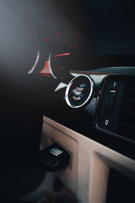
The ignition switch serves as the control center for the ignition system, routing power to the battery, starter motor, and ignition coil. It operates in multiple positions (OFF, RUN, START), enabling precise power distribution. The switch ensures safe and efficient operation by activating essential components only when needed, preventing unauthorized use and electrical issues.
Ignition Switch Positions
The ignition switch operates in three primary positions: OFF, RUN, and START. In the OFF position, all electrical systems are deactivated. The RUN position powers the ignition system, fuel pump, and accessories while the engine runs. The START position engages the starter motor to crank the engine; it automatically returns to RUN once the engine starts. Understanding these positions is crucial for diagnosing issues and ensuring proper electrical flow. Always refer to the wiring diagram for specific configurations and safety guidelines.
Power Distribution Through the Switch
The ignition switch acts as the central control point for power distribution in the ignition system, directing electrical flow to various components. In the OFF position, it disconnects power to all systems. The RUN position powers the ignition coil, fuel pump, and accessories, while maintaining battery connection. The START position energizes the starter motor temporarily. The switch ensures power is routed efficiently, preventing overloading and ensuring proper system operation. Always consult the wiring diagram to understand specific circuit paths and connections for accurate repairs and safety.

Troubleshooting Common Issues
Troubleshooting ignition system issues involves identifying faults like no power, intermittent connections, or failure to start. Always refer to the wiring diagram to locate and repair damaged components or connections.
No Power to the Ignition System
No power to the ignition system can occur due to a disconnected battery, blown fuse, or faulty ignition switch. Check the wiring diagram to identify connections between the battery, ignition switch, and components. Verify the ignition switch’s functionality and ensure all terminals are clean. A bad ignition coil or broken circuit can also cause this issue. Use a multimeter to test voltage at key points, ensuring power flows correctly through the system. Always consult a vehicle-specific wiring diagram for accurate troubleshooting and repairs.
Intermittent Electrical Issues
Intermittent electrical issues can be challenging to diagnose, as they occur sporadically. These issues often stem from loose connections, corroded terminals, or a faulty ignition switch. Consult the wiring diagram to trace the circuit and identify potential weak points. Inspect connectors for damage or oxidation and test the ignition switch for consistent power delivery. Use a multimeter to check voltage fluctuations and continuity in wires. Addressing these issues promptly prevents further damage and ensures reliable system operation. Always refer to a vehicle-specific wiring diagram for accurate troubleshooting.
Car Not Starting
If your car fails to start, the ignition switch or its wiring may be at fault. Check the wiring diagram to ensure the ignition switch is sending power to the starter motor and fuel pump. A faulty ignition switch can prevent the necessary electrical signals from reaching these components. Look for open circuits, blown fuses, or loose connections in the wiring. Use a multimeter to test the ignition switch’s output and verify continuity in critical circuits. Consult the wiring diagram to trace the circuit and identify potential failure points. Always refer to a vehicle-specific diagram for accurate troubleshooting.
Safety Precautions
Always disconnect the battery before working on ignition systems to prevent electrical shocks or fires. Use insulated tools and follow wiring diagrams to avoid short circuits or misconnections.
Working with Electrical Systems
When working with ignition systems, always disconnect the battery to prevent electrical shocks or fires. Use insulated tools to handle live wires and avoid short circuits. Ensure proper grounding and consult the wiring diagram for specific connections. Never bypass safety components like fuses or circuit breakers, as this can lead to system damage or fire hazards. Wear protective gear, including gloves and safety glasses, to minimize risks during repairs or installations.
Avoiding Short Circuits
Avoiding short circuits is crucial when working with ignition systems. Ensure all wires are properly insulated and secured to prevent unintended contact. Use circuit breakers or fuses to protect against overcurrent situations. Always refer to the wiring diagram to confirm connections are correct. Never bypass safety components, as this can lead to short circuits and potential fires. Regularly inspect wires for damage or wear and replace them if necessary. Properly grounding the system is also essential to prevent electrical hazards and ensure reliable operation.
Proper Use of Tools
Using the correct tools ensures safe and effective work with ignition systems. Wire cutters, strippers, and crimpers are essential for modifying or repairing connections. Multimeters help diagnose electrical issues accurately. Always use insulated tools to prevent shocks. Refer to the wiring diagram to identify the right tools for specific tasks. Proper tool usage prevents damage to components and ensures reliable repairs. Avoid using makeshift tools, as they may cause short circuits or improper connections. Regularly maintain tools to guarantee precision and safety during electrical work.
Downloading and Using a PDF Guide
A PDF guide provides detailed ignition switch wiring diagrams, making it easier to understand and repair electrical circuits. Download from reliable sources like throttleaddiction.com or official manufacturer websites. Ensure the diagram matches your vehicle model for accuracy. Use zoom tools to view small details and refer to the guide alongside your wiring diagram for effective troubleshooting and installation.
Where to Find Reliable Wiring Diagrams
Reliable ignition switch wiring diagrams can be found on reputable automotive websites, manufacturer portals, and forums. Websites like throttleaddiction.com offer downloadable PDF guides for specific models. Official manufacturer websites, such as Ford or Briggs and Stratton, provide accurate diagrams for their engines. Additionally, automotive repair forums and databases like AllData or AutoZone offer detailed wiring schematics; Always verify the diagram matches your vehicle’s make and model for precision. Ensure the source is trustworthy to avoid incorrect or unsafe wiring information.

How to Use the PDF Guide Effectively
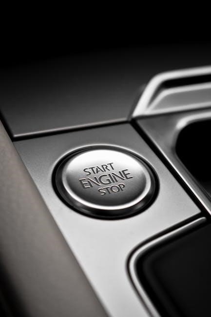
To effectively use an ignition switch wiring diagram PDF, start by locating the specific diagram for your vehicle’s make and model. Cross-reference the diagram with your vehicle’s repair manual for accuracy. Pay attention to color coding and symbols, which indicate wire connections and component locations. Use the diagram to trace circuits and identify potential issues. When making repairs, follow the sequence outlined in the guide to ensure proper reconnection. Testing each component as you go can help verify the system’s functionality. Always refer back to the PDF for clarity during complex steps.
Installation and Replacement Tips
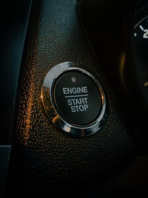
Consult the ignition switch wiring diagram PDF for specific instructions. Disconnect the battery before starting work to ensure safety. Match wires by color and function, following the diagram precisely. Test the ignition system after installation to confirm proper functionality.
Steps to Replace the Ignition Switch
To replace the ignition switch, start by disconnecting the battery to prevent electrical shocks. Remove the trim and screws around the switch, then gently pull it out. Disconnect the wiring harness, noting the connections from the wiring diagram. Install the new switch, ensuring it aligns properly with the mounting bracket. Reconnect the wires according to the diagram, starting with the battery and ignition circuits. Test the switch by turning the key through all positions. Reassemble the dash and reconnect the battery. Verify functionality by starting the engine and checking all electrical systems.
Tools and Materials Needed
Replacing an ignition switch requires specific tools and materials. Essential tools include a screwdriver set, pliers, and a wrench for disassembly. A wiring diagram is crucial for identifying connections. Additional materials like electrical tape, a multimeter, and a soldering iron may be needed for repairs. A replacement ignition switch, mounting screws, and a torque wrench ensure proper installation. Always refer to the wiring diagram for vehicle-specific requirements to avoid errors and ensure safety during the process.

Vechicle-Specific Wiring Diagrams
Vechicle-specific wiring diagrams are tailored to particular models and years, ensuring accurate repairs. They detail exact connections for ignition switches, starters, and related components, optimizing safety and efficiency.
Car Ignition Switch Wiring
Car ignition switch wiring diagrams detail the electrical connections for automotive ignition systems. These diagrams show how the ignition switch interfaces with the battery, starter motor, ignition coil, and accessories. They often include color-coded wires to simplify identification; For example, the S10 ignition switch diagram highlights connections for power, start, and accessory functions. Always use vehicle-specific diagrams to ensure accuracy, as wiring layouts vary by make and model. Referencing the correct PDF guide helps in diagnosing issues like no power or intermittent starting problems, ensuring safe and effective repairs.
Motorcycle Ignition Switch Wiring
Motorcycle ignition switch wiring diagrams provide a detailed layout of the electrical connections for bike ignition systems. These diagrams typically include the ignition switch, battery, starter motor, and ignition coil. They often highlight specific circuits for accessories like lights or horns. For example, a Sportster wiring diagram shows connections for power, start, and accessory functions. Using a PDF guide ensures accurate repairs, as wiring layouts vary by model. Always reference vehicle-specific diagrams to diagnose issues like faulty starts or electrical malfunctions, ensuring safe and efficient troubleshooting.
Boat Ignition Switch Wiring
Boat ignition switch wiring diagrams outline the electrical connections for marine ignition systems, ensuring safe and efficient operation. These diagrams typically detail connections to the battery, starter motor, and ignition coil, while also addressing marine-specific components like bilge pumps or navigation lights. They often highlight circuits for accessories and safety systems. Using a PDF guide specific to your boat model helps in troubleshooting common marine electrical issues, such as corrosion or moisture-related faults. Always refer to vehicle-specific diagrams for accurate and reliable repairs, ensuring optimal performance and safety on the water.
An ignition switch wiring diagram is essential for understanding and repairing electrical systems efficiently. PDF guides offer clear schematics, ensuring safety and functionality. Use them accurately for reliable and effective outcomes;
Final Thoughts
Understanding and using an ignition switch wiring diagram is crucial for effective troubleshooting and installation. PDF guides provide comprehensive visuals and instructions, ensuring accurate repairs. Always prioritize safety by following proper procedures and using correct tools. Regularly update your knowledge with the latest diagrams and resources. For complex issues, consulting a professional is advisable. Remember, a well-maintained ignition system ensures reliability and optimal vehicle performance. Keep PDF guides handy for quick reference and to avoid costly mistakes. Safe and successful repairs start with clear, detailed wiring diagrams.
Additional Resources
For further assistance, download PDF guides from trusted automotive websites like ThrottleAddiction or BriggsAndStratton. These resources offer detailed wiring diagrams and step-by-step instructions. Vehicle-specific manuals, such as those for Sportsman 700/800 EFI or GMC Wiring Diagrams, provide tailored information. Online forums and repair communities also share valuable insights and troubleshooting tips. Always cross-reference diagrams with your vehicle’s make and model for accuracy. These resources ensure you have comprehensive support for ignition system repairs and maintenance.
